Engineering Specifications for Connext Products
Connector specifications are made available for use by engineering firms, architects, contractors and designers. Review below or click to download these specifications. PDF and DXF files for connectors are available under Product Drawings.
Engineering Design Basis Letter
The letter below outlines the official engineering methodology used for Connext connectors, prepared and approved by a licensed Professional Engineer in accordance with NDS standards.
(Click here to download in PDF format.)
Final design approval remains the responsibility of the project engineer or local building official.
November 5th, 2025
Connext connectors have been designed according to National Design Specification for Wood
Design (NDS) dowel bearing equations listed in chapter 12. The capacities were determined using
connector material properties and accepted engineering practice outlined in the NDS, which is further approved by standard building codes. Use of these connectors is to be approved by the practicing engineer of the project or local building official; however, these values are provided to speed along design and use. This document does not absolve the installer of due diligence to assure the connectors are used in a safe and appropriate manner.
Submitted by:
Michael Prast, MSCE, P.E.
Fire Tower Engineered Timber, Inc.

Load Definitions
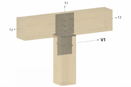
Connector capacities below are reported using three primary load directions: T, V1, and V2. These represent the standardized force components used in structural engineering and are consistent with National Design Specification (NDS) methodology.
T — Tension / Uplift (Tear-Out): T represents axial tension along the length of the beam or post. This is the force trying to pull the beam straight out of the connector along the knife, such as uplift from wind or seismic loads.
V1 - V1 represents shear acting parallel to the knife. This is the typical downward load from the supported beam, such as roof or floor weight transferring into the post. In the case of these connectors, the direction of V1 can be either way. For corner and splice connectors, the load direction would be horizontal.
V2 — Lateral Shear (Across the Flange): V2 represents horizontal shear across the connector flange. This is the force trying to slide the beam sideways, perpendicular relative to the knife, such as lateral loads from wind, seismic activity, or unbalanced framing. High loads in this direction often require extra reinforcing of the wood.
Post-to-Beam Loading Diagram & Connection Capacities
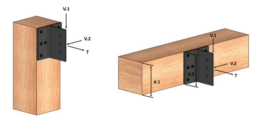
Post-to-Beam Connector Capacities
When determining load allowables for Connext post-to-beam connectors please reference the table below.
Swipe horizontally to view full engineering table →
| Connector Size | Screw Size | # of Screws | # of Pins3 | Timber Species5,8 | Load Duration, Cd4 | T | V1 | V2 |
|---|---|---|---|---|---|---|---|---|
| 3.5” × 3.5” | ¼” × 2 ¾” | 4 | 2 (3.5” Long) | EWP (G=0.36) | 1.0 | 840 | 647 | 107 |
| DF (G=0.5) | 1.0 | 1,375 | 867 | 145 | ||||
| R. Oak (G=0.67) | 1.0 | 1,406 | 1,123 | 133 | ||||
| 4” × 6” | 3-⅛” | 4 | 2 (4” Long) | EWP (G=0.36) | 1.0 | 1,258 | 876 | 204 |
| DF (G=0.5) | 1.0 | 2,060 | 1,137 | 278 | ||||
| R. Oak (G=0.67) | 1.0 | 3,195 | 1,416 | 253 | ||||
| 4” × 8” | 3-⅛” | 6 | 3 (4” Long) | EWP (G=0.36) | 1.0 | 1,888 | 1,334 | 272 |
| DF (G=0.5) | 1.0 | 3,090 | 1,733 | 371 | ||||
| R. Oak (G=0.67) | 1.0 | 4,793 | 2,157 | 338 | ||||
| 5.5” × 5.5” | 3-⅛” | 6 | 2 | EWP (G=0.36) | 1.0 | 1,888 | 1,334 | 272 |
| DF (G=0.5) | 1.0 | 3,090 | 1,733 | 371 | ||||
| R. Oak (G=0.67) | 1.0 | 3,656 | 2,157 | 338 | ||||
| 5-⅛” | 6 | 2 | EWP (G=0.36) | 1.0 | 3,037 | 1,334 | 272 | |
| DF (G=0.5) | 1.0 | 3,656 | 1,733 | 371 | ||||
| R. Oak (G=0.67) | 1.0 | 3,656 | 2,157 | 338 | ||||
| 5.5” × 7.5” | 3-⅛” | 6 | 2 | EWP (G=0.36) | 1.0 | 1,888 | 1,334 | 372 |
| DF (G=0.5) | 1.0 | 3,090 | 1,733 | 505 | ||||
| R. Oak (G=0.67) | 1.0 | 3,656 | 2,157 | 461 | ||||
| 5-⅛” | 6 | 2 | EWP (G=0.36) | 1.0 | 3,037 | 1,334 | 372 | |
| DF (G=0.5) | 1.0 | 3,656 | 1,733 | 505 | ||||
| R. Oak (G=0.67) | 1.0 | 3,656 | 2,157 | 461 | ||||
| 5.5” × 9.5” | 3-⅛” | 6 | 3 | EWP (G=0.36) | 1.0 | 1,888 | 1,334 | 471 |
| DF (G=0.5) | 1.0 | 3,090 | 1,733 | 640 | ||||
| R. Oak (G=0.67) | 1.0 | 4,793 | 2,157 | 584 | ||||
| 5-⅛” | 6 | 3 | EWP (G=0.36) | 1.0 | 3,109 | 1,334 | 471 | |
| DF (G=0.5) | 1.0 | 5,089 | 1,733 | 640 | ||||
| R. Oak (G=0.67) | 1.0 | 5,484 | 2,157 | 584 | ||||
| 5.5” × 11.5” | 3-⅛” | 6 | 3 | EWP (G=0.36) | 1.0 | 1,888 | 1,376 | 570 |
| DF (G=0.5) | 1.0 | 3,090 | 1,786 | 775 | ||||
| R. Oak (G=0.67) | 1.0 | 4,793 | 2,224 | 707 | ||||
| 5-⅛” | 6 | 3 | EWP (G=0.36) | 1.0 | 3,109 | 1,376 | 570 | |
| DF (G=0.5) | 1.0 | 5,089 | 1,786 | 775 | ||||
| R. Oak (G=0.67) | 1.0 | 5,484 | 2,224 | 707 | ||||
| 6” × 6” | 3-⅛” | 6 | 2 | EWP (G=0.36) | 1.0 | 1,888 | 1,334 | 328 |
| DF (G=0.5) | 1.0 | 3,090 | 1,733 | 447 | ||||
| R. Oak (G=0.67) | 1.0 | 3,656 | 2,157 | 407 | ||||
| 5-⅛” | 6 | 2 | EWP (G=0.36) | 1.0 | 3,037 | 1,334 | 328 | |
| DF (G=0.5) | 1.0 | 3,656 | 1,733 | 447 | ||||
| R. Oak (G=0.67) | 1.0 | 3,656 | 2,157 | 407 | ||||
| 6” × 8” | 3-⅛” | 6 | 2 | EWP (G=0.36) | 1.0 | 1,888 | 1,334 | 438 |
| DF (G=0.5) | 1.0 | 3,090 | 1,733 | 595 | ||||
| R. Oak (G=0.67) | 1.0 | 3,656 | 2,157 | 461 | ||||
| 5-⅛” | 6 | 2 | EWP (G=0.36) | 1.0 | 3,037 | 1,334 | 438 | |
| DF (G=0.5) | 1.0 | 3,656 | 1,733 | 595 | ||||
| R. Oak (G=0.67) | 1.0 | 3,656 | 2,157 | 543 | ||||
| 6” × 10” | 3-⅛” | 6 | 3 | EWP (G=0.36) | 1.0 | 1,888 | 1,334 | 547 |
| DF (G=0.5) | 1.0 | 3,090 | 1,733 | 744 | ||||
| R. Oak (G=0.67) | 1.0 | 4,793 | 2,157 | 679 | ||||
| 5-⅛” | 6 | 3 | EWP (G=0.36) | 1.0 | 3,109 | 1,334 | 547 | |
| DF (G=0.5) | 1.0 | 5,089 | 1,733 | 744 | ||||
| R. Oak (G=0.67) | 1.0 | 5,484 | 2,157 | 679 | ||||
| 6” × 12” | 3-⅛” | 6 | 3 | EWP (G=0.36) | 1.0 | 1,888 | 1,376 | 657 |
| DF (G=0.5) | 1.0 | 3,090 | 1,786 | 893 | ||||
| R. Oak (G=0.67) | 1.0 | 4,793 | 2,224 | 814 | ||||
| 5-⅛” | 6 | 3 | EWP (G=0.36) | 1.0 | 3,109 | 1,376 | 657 | |
| DF (G=0.5) | 1.0 | 5,089 | 1,786 | 893 | ||||
| R. Oak (G=0.67) | 1.0 | 5,484 | 2,224 | 814 | ||||
| 7.5” × 7.5” | 3-⅛” | 8 | 3 | EWP (G=0.36) | 1.0 | 2,517 | 2,054 | 521 |
| DF (G=0.5) | 1.0 | 4,120 | 2,652 | 708 | ||||
| R. Oak (G=0.67) | 1.0 | 6,117 | 3,280 | 645 | ||||
| 5-⅛” | 8 | 3 | EWP (G=0.36) | 1.0 | 4,145 | 2,054 | 521 | |
| DF (G=0.5) | 1.0 | 5,631 | 2,652 | 708 | ||||
| R. Oak (G=0.67) | 1.0 | 6,117 | 3,280 | 645 | ||||
| 7.5” × 9.5” | 3-⅛” | 8 | 3 | EWP (G=0.36) | 1.0 | 2,517 | 2,054 | 659 |
| DF (G=0.5) | 1.0 | 4,120 | 2,652 | 897 | ||||
| R. Oak (G=0.67) | 1.0 | 6,117 | 3,280 | 818 | ||||
| 5-⅛” | 8 | 3 | EWP (G=0.36) | 1.0 | 4,145 | 2,054 | 659 | |
| DF (G=0.5) | 1.0 | 5,631 | 2,652 | 897 | ||||
| R. Oak (G=0.67) | 1.0 | 6,117 | 3,280 | 818 | ||||
| 7.5” × 11.5” | 3-⅛” | 8 | 3 | EWP (G=0.36) | 1.0 | 2,517 | 2,054 | 798 |
| DF (G=0.5) | 1.0 | 4,120 | 2,652 | 1,086 | ||||
| R. Oak (G=0.67) | 1.0 | 6,117 | 3,280 | 990 | ||||
| 5-⅛” | 8 | 3 | EWP (G=0.36) | 1.0 | 4,145 | 2,054 | 798 | |
| DF (G=0.5) | 1.0 | 5,631 | 2,652 | 1,086 | ||||
| R. Oak (G=0.67) | 1.0 | 6,117 | 3,280 | 990 | ||||
| 8” × 8” | 3-⅛” | 8 | 3 | EWP (G=0.36) | 1.0 | 2,517 | 2,054 | 597 |
| DF (G=0.5) | 1.0 | 4,120 | 2,652 | 812 | ||||
| R. Oak (G=0.67) | 1.0 | 6,117 | 3,280 | 740 | ||||
| 5-⅛” | 8 | 3 | EWP (G=0.36) | 1.0 | 4,145 | 2,054 | 597 | |
| DF (G=0.5) | 1.0 | 5,631 | 2,652 | 812 | ||||
| R. Oak (G=0.67) | 1.0 | 6,117 | 3,280 | 740 | ||||
| 8” × 10” | 3-⅛” | 8 | 3 | EWP (G=0.36) | 1.0 | 2,517 | 2,101 | 746 |
| DF (G=0.5) | 1.0 | 4,120 | 2,713 | 1,014 | ||||
| R. Oak (G=0.67) | 1.0 | 6,117 | 3,356 | 925 | ||||
| 5-⅛” | 8 | 3 | EWP (G=0.36) | 1.0 | 4,145 | 2,101 | 746 | |
| DF (G=0.5) | 1.0 | 5,631 | 2,713 | 1,014 | ||||
| R. Oak (G=0.67) | 1.0 | 6,117 | 3,356 | 925 | ||||
| 8” × 12” | 3-⅛” | 8 | 3 | EWP (G=0.36) | 1.0 | 2,517 | 2,101 | 895 |
| DF (G=0.5) | 1.0 | 4,120 | 2,713 | 1,217 | ||||
| R. Oak (G=0.67) | 1.0 | 6,117 | 3,356 | 1,110 | ||||
| 5-⅛” | 8 | 3 | EWP (G=0.36) | 1.0 | 4,145 | 2,101 | 895 | |
| DF (G=0.5) | 1.0 | 5,631 | 2,713 | 1,217 | ||||
| R. Oak (G=0.67) | 1.0 | 6,117 | 3,356 | 1,110 | ||||
| 10” × 10” | 3-⅛” | 12 | 3 | EWP (G=0.36) | 1.0 | 3,775 | 2,748 | 954 |
| DF (G=0.5) | 1.0 | 5,631 | 3,451 | 1,297 | ||||
| R. Oak (G=0.67) | 1.0 | 6,117 | 4,209 | 1,183 | ||||
| 5-⅛” | 12 | 3 | EWP (G=0.36) | 1.0 | 4,840 | 2,748 | 954 | |
| DF (G=0.5) | 1.0 | 5,631 | 3,451 | 1,297 | ||||
| R. Oak (G=0.67) | 1.0 | 6,117 | 4,209 | 1,183 | ||||
| 12” × 12” | 3-⅛” | 12 | 3 | EWP (G=0.36) | 1.0 | 3,775 | 2,748 | 1,394 |
| DF (G=0.5) | 1.0 | 5,631 | 3,451 | 1,896 | ||||
| R. Oak (G=0.67) | 1.0 | 6,117 | 4,209 | 1,728 | ||||
| 5-⅛” | 12 | 3 | EWP (G=0.36) | 1.0 | 4,840 | 2,748 | 1,394 | |
| DF (G=0.5) | 1.0 | 5,631 | 3,451 | 1,896 | ||||
| R. Oak (G=0.67) | 1.0 | 6,117 | 4,209 | 1,728 |
1 Capacities for species not shown may be linearly interpolated based on specific gravity.
2 Pins are ½” diameter and assumed to be 3.5” minimum length for 4x connectors, 5” minimum length for 6x connectors, 7” minimum for 8x connectors, 9” minimum for 10x connectors, and 11” minimum for 12x connectors.
3 Capacities can be adjusted for Load Duration Factors other than 1.0.
4 Assumes the beam and post are the same species.
5 Connectors and pins are 6061 aluminum.
6 EWP = Eastern White Pine, DF = Douglas-Fir-Larch, R. Oak = Red Oak.
7 When using larger connectors in configuration B, review cross shrinkage effects for individual timber conditions.
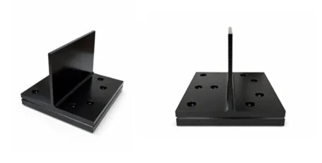
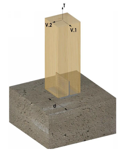
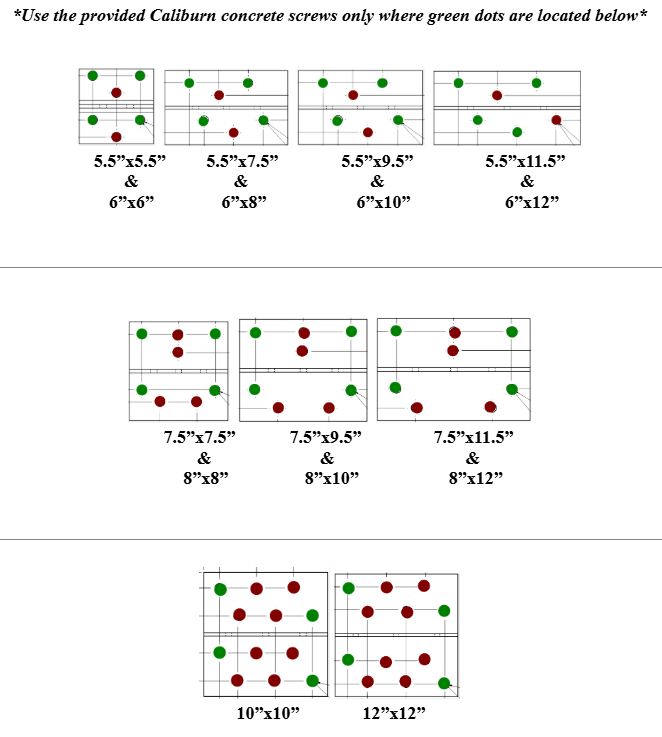
Post-to-Base (Concrete) Loading Diagram & Screw Hole Patterns
Tighter spacing and increased number of concrete screws can be used in lieu of the guidelines listed in ESR-3251 for GRK Caliburns with proper engineering guidance.
Post-to-Base Connector Capacities
When determining load allowables for Connext post-to-base connectors please reference the table below:
Swipe horizontally to view full engineering table →
| Connector | # of Screws | # of Pins2 | Timber Species | Load Duration, Cd3 | T | V1 | V24 |
|---|---|---|---|---|---|---|---|
| 3.5” × 3.5” | 2 | 2 (3.5” Long) | EWP (G=0.36) | 1.0 | 1,268 | 647 | 107 |
| DF (G=0.5) | 1.0 | 1,406 | 867 | 145 | |||
| R. Oak (G=0.67) | 1.0 | 1,406 | 1,125 | 133 | |||
| 4” × 6” | 2 | 2 (4” Long) | EWP (G=0.36) | 1.0 | 2,673 | 1,340 | 204 |
| DF (G=0.5) | 1.0 | 3,398 | 1,808 | 278 | |||
| R. Oak (G=0.67) | 1.0 | 3,656 | 2,434 | 253 | |||
| 4” × 8” | 3 | 3 (4” Long) | EWP (G=0.36) | 1.0 | 4,010 | 2,017 | 272 |
| DF (G=0.5) | 1.0 | 5,097 | 2,711 | 371 | |||
| R. Oak (G=0.67) | 1.0 | 5,484 | 3,651 | 338 | |||
| 5.5” × 5.5” | 4 | 2 | EWP (G=0.36) | 1.0 | 3,037 | 1,345 | 272 |
| DF (G=0.5) | 1.0 | 3,656 | 1,889 | 371 | |||
| R. Oak (G=0.67) | 1.0 | 3,656 | 2,627 | 338 | |||
| 5.5” × 7.5” | 4 | 2 | EWP (G=0.36) | 1.0 | 3,037 | 1,435 | 372 |
| DF (G=0.5) | 1.0 | 3,656 | 2,015 | 505 | |||
| R. Oak (G=0.67) | 1.0 | 3,656 | 2,803 | 461 | |||
| 5.5” × 9.5” | 4 | 3 | EWP (G=0.36) | 1.0 | 4,556 | 2,153 | 471 |
| DF (G=0.5) | 1.0 | 5,484 | 3,022 | 640 | |||
| R. Oak (G=0.67) | 1.0 | 5,484 | 4,204 | 584 | |||
| 5.5” × 11.5” | 4 | 3 | EWP (G=0.36) | 1.0 | 4,556 | 2,153 | 570 |
| DF (G=0.5) | 1.0 | 5,484 | 3,022 | 775 | |||
| R. Oak (G=0.67) | 1.0 | 5,484 | 4,204 | 707 | |||
| 6” × 6” | 4 | 2 | EWP (G=0.36) | 1.0 | 3,037 | 1,435 | 328 |
| DF (G=0.5) | 1.0 | 3,656 | 2,015 | 447 | |||
| R. Oak (G=0.67) | 1.0 | 3,656 | 2,803 | 407 | |||
| 6” × 8” | 4 | 2 | EWP (G=0.36) | 1.0 | 3,037 | 1,435 | 438 |
| DF (G=0.5) | 1.0 | 3,656 | 2,015 | 595 | |||
| R. Oak (G=0.67) | 1.0 | 3,656 | 2,803 | 543 | |||
| 6” × 10” | 4 | 3 | EWP (G=0.36) | 1.0 | 4,556 | 2,153 | 547 |
| DF (G=0.5) | 1.0 | 5,484 | 3,022 | 744 | |||
| R. Oak (G=0.67) | 1.0 | 5,484 | 4,204 | 679 | |||
| 6” × 12” | 4 | 3 | EWP (G=0.36) | 1.0 | 4,556 | 2,153 | 657 |
| DF (G=0.5) | 1.0 | 5,484 | 3,022 | 893 | |||
| R. Oak (G=0.67) | 1.0 | 5,484 | 4,204 | 814 | |||
| 7.5” × 7.5” | 4 | 3 | EWP (G=0.36) | 1.0 | 4,840 | 2,502 | 521 |
| DF (G=0.5) | 1.0 | 5,631 | 3,382 | 708 | |||
| R. Oak (G=0.67) | 1.0 | 6,117 | 4,124 | 645 | |||
| 7.5” × 9.5” | 4 | 3 | EWP (G=0.36) | 1.0 | 4,840 | 2,553 | 659 |
| DF (G=0.5) | 1.0 | 5,631 | 3,451 | 897 | |||
| R. Oak (G=0.67) | 1.0 | 6,117 | 4,209 | 818 | |||
| 7.5” × 11.5” | 4 | 3 | EWP (G=0.36) | 1.0 | 4,840 | 2,553 | 798 |
| DF (G=0.5) | 1.0 | 5,631 | 3,451 | 1,086 | |||
| R. Oak (G=0.67) | 1.0 | 6,117 | 4,209 | 990 | |||
| 8” × 8” | 4 | 3 | EWP (G=0.36) | 1.0 | 4,840 | 2,553 | 597 |
| DF (G=0.5) | 1.0 | 5,631 | 3,451 | 812 | |||
| R. Oak (G=0.67) | 1.0 | 6,117 | 4,209 | 740 | |||
| 8” × 10” | 4 | 3 | EWP (G=0.36) | 1.0 | 4,840 | 2,553 | 746 |
| DF (G=0.5) | 1.0 | 5,631 | 3,451 | 1,014 | |||
| R. Oak (G=0.67) | 1.0 | 6,117 | 4,209 | 925 | |||
| 8” × 12” | 4 | 3 | EWP (G=0.36) | 1.0 | 4,840 | 2,553 | 895 |
| DF (G=0.5) | 1.0 | 5,631 | 3,451 | 1,217 | |||
| R. Oak (G=0.67) | 1.0 | 6,117 | 4,209 | 1,110 | |||
| 9.5” × 9.5” | 4 | 3 | EWP (G=0.36) | 1.0 | 4,840 | 2,748 | 857 |
| DF (G=0.5) | 1.0 | 5,631 | 3,451 | 1,165 | |||
| R. Oak (G=0.67) | 1.0 | 6,117 | 4,209 | 1,062 | |||
| 10” × 10” | 4 | 3 | EWP (G=0.36) | 1.0 | 4,840 | 2,748 | 954 |
| DF (G=0.5) | 1.0 | 5,631 | 3,451 | 1,297 | |||
| R. Oak (G=0.67) | 1.0 | 6,117 | 4,209 | 1,183 | |||
| 11.5” × 11.5” | 4 | 3 | EWP (G=0.36) | 1.0 | 4,840 | 2,748 | 1,276 |
| DF (G=0.5) | 1.0 | 5,631 | 3,451 | 1,735 | |||
| R. Oak (G=0.67) | 1.0 | 6,117 | 4,209 | 1,582 | |||
| 12” × 12” | 4 | 3 | EWP (G=0.36) | 1.0 | 4,840 | 2,748 | 1,394 |
| DF (G=0.5) | 1.0 | 5,631 | 3,451 | 1,896 | |||
| R. Oak (G=0.67) | 1.0 | 6,117 | 4,209 | 1,728 |
Table 3 - Post-To-Base Connection Capacity
1 Capacities for species not shown may be linearly interpolated based on specific gravity.
2 Pins are ½” diameter and assumed to be 3.5” minimum length for 4x connectors, 5” minimum length for 6x connectors, 7” minimum for 8x connectors, 9” minimum for 10x connectors, and 11” minimum for 12x connectors.
3 Capacities can be adjusted for Load Duration Factors other than 1.0.
4 Connector and pins are 6061 aluminum.
5 EWP = Eastern White Pine, DF = Douglas-Fir-Larch, R. Oak = Red Oak.
6 Base is designed to hold 19/64” diameter, 5” long GRK Caliburn screws into concrete.
Table Notes:
The post bases' anchorage can develop the ½T, ½V1, and full V2 capacity of the wood values listed in the table provided the bases are installed under the following conditions:
- Concrete is at least 6” thick.
- Screw anchors have at least 3” embedment into the concrete.
- There is a minimum of 6” in any direction from the screw anchors to the edge of concrete or reduction in thickness, whichever the condition is.
- The concrete has a compressive capacity of at least 3,000 psi.
- Assumed uncracked concrete in design.
- No additional rebar reinforcement considered.
The above capacities are for the timber only and do not include the concrete screws and resistance of the concrete foundation to breakout, side-face blowout, or pryout beyond the conditions listed above. If conditions differ from what is listed, determination of the resistance for these limit states is the responsibility of a qualified design professional for each site-specific condition. If the full tension or shear capacity of the connector is required, inquire with a design professional about alternative anchorage. The concrete design and unique edge distance conditions are too variable to be comprehensibly listed here.
Post bases can be installed directly to the concrete. If the post base sits atop a 2x sill plate or riser rather than directly on the concrete, further design of the concrete anchors is required.
Diagonal Connectors Loading Diagram
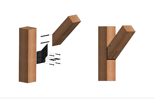
Diagonal Connector Capacities
When determining load allowables for Connext diagonal connectors please reference the tables below.
Swipe horizontally to view full engineering table →
| Connector Size | Screw Size | # of Screws | # of Pins2 | Timber Species4,6 | Load Duration, Cd3 | T | V |
|---|---|---|---|---|---|---|---|
| 5.5” × 7.5” (fits 5.5” × 5.5” beam) |
3-⅛” | 6 | 2 | EWP (G=0.36) | 1.0 | 1,592 | 1,376 |
| DF (G=0.5) | 1.0 | 2,264 | 1,786 | ||||
| R. Oak (G=0.67) | 1.0 | 3,039 | 2,224 | ||||
| 5-⅛” | 6 | 2 | EWP (G=0.36) | 1.0 | 1,908 | 1,376 | |
| DF (G=0.5) | 1.0 | 2,645 | 1,786 | ||||
| R. Oak (G=0.67) | 1.0 | 3,472 | 2,224 | ||||
| 6” × 8.5” (fits 6” × 6” beam) |
3-⅛” | 6 | 2 | EWP (G=0.36) | 1.0 | 1,592 | 1,376 |
| DF (G=0.5) | 1.0 | 2,264 | 1,786 | ||||
| R. Oak (G=0.67) | 1.0 | 3,039 | 2,224 | ||||
| 5-⅛” | 6 | 2 | EWP (G=0.36) | 1.0 | 1,908 | 1,376 | |
| DF (G=0.5) | 1.0 | 2,645 | 1,786 | ||||
| R. Oak (G=0.67) | 1.0 | 3,472 | 2,224 | ||||
| 7.5” × 10.5” (fits 7.5” × 7.5” beam) |
3-⅛” | 8 | 3 | EWP (G=0.36) | 1.0 | 2,290 | 2,101 |
| DF (G=0.5) | 1.0 | 3,272 | 2,713 | ||||
| R. Oak (G=0.67) | 1.0 | 4,402 | 3,356 | ||||
| 5-⅛” | 8 | 3 | EWP (G=0.36) | 1.0 | 2,789 | 2,101 | |
| DF (G=0.5) | 1.0 | 3,877 | 2,713 | ||||
| R. Oak (G=0.67) | 1.0 | 5,091 | 3,356 | ||||
| 8” × 11.5” (fits 8” × 8” beam) |
3-⅛” | 8 | 3 | EWP (G=0.36) | 1.0 | 2,290 | 2,101 |
| DF (G=0.5) | 1.0 | 3,272 | 2,713 | ||||
| R. Oak (G=0.67) | 1.0 | 4,402 | 3,356 | ||||
| 5-⅛” | 8 | 3 | EWP (G=0.36) | 1.0 | 2,789 | 2,101 | |
| DF (G=0.5) | 1.0 | 3,877 | 2,713 | ||||
| R. Oak (G=0.67) | 1.0 | 5,091 | 3,356 |
Table 4
1 Capacities for species not shown may be linearly interpolated based on specific gravity.
2 Pins are ½” diameter and assumed to be 5” minimum length for 6x connectors and 7” minimum for 8x connectors.
3 Capacities can be adjusted for Load Duration Factors other than 1.0.
4 Assumes the brace and post are the same species.
5 Connectors and pins are 6061 aluminum.
6 EWP = Eastern White Pine, DF = Douglas-Fir-Larch, R. Oak = Red Oak.
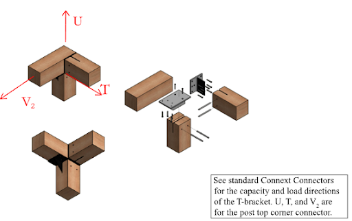
Multi-Beam Connectors Loading Diagrams & Connection Capacities
Corner Connector Loading Diagram
Splice Connector Loading Diagram
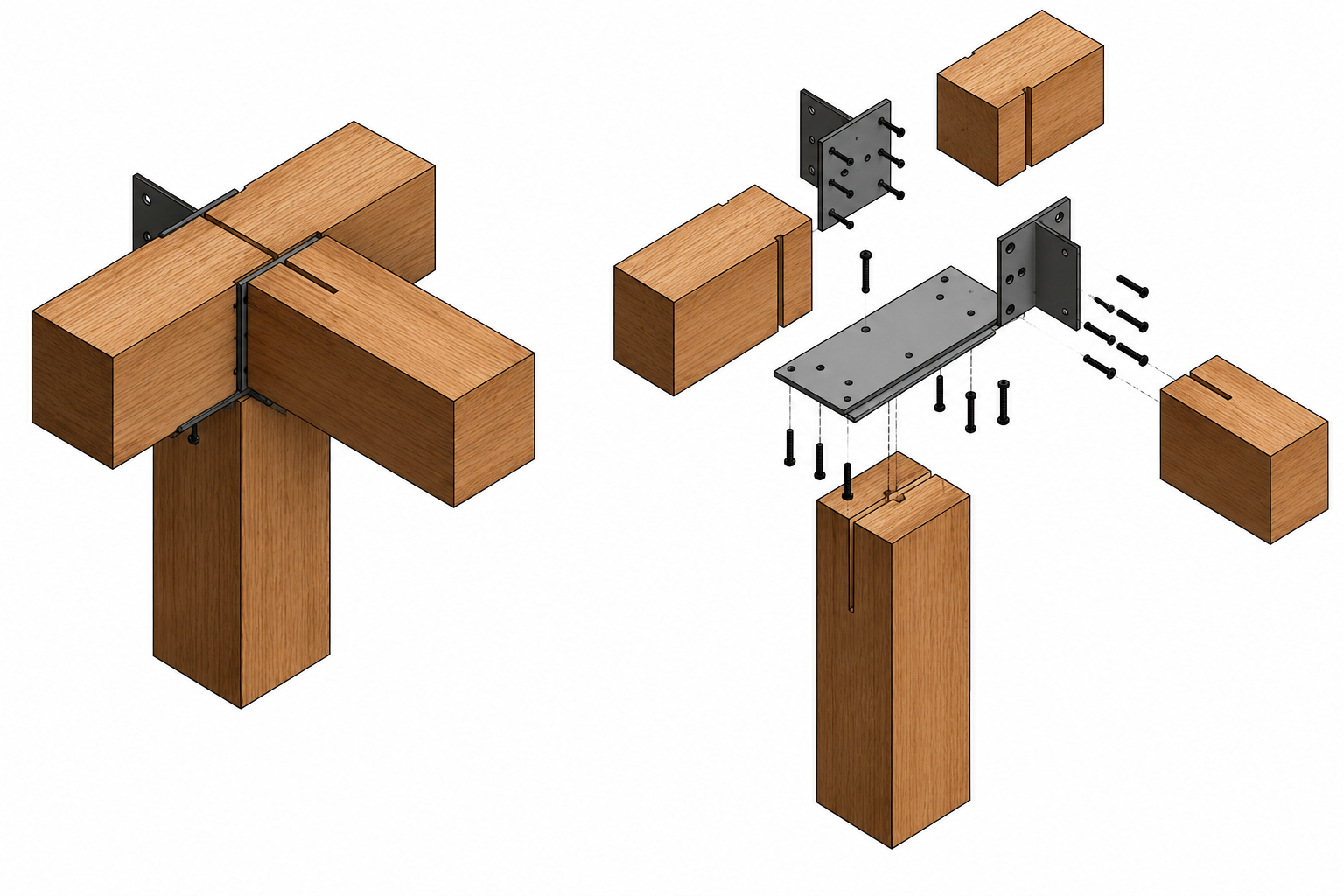
Multi-Beam Connector Capacities (Corner & Splice Connectors)
When determining load allowables for Connext multi-beam connectors please reference the tables below.
Swipe horizontally to view full engineering table →
| Connector | Screw Size | # of Screws | # of Pins | Timber Species | Load Duration, Cd | T | U | V2 |
|---|---|---|---|---|---|---|---|---|
| 5.5” Corner | 3-⅛” | 4 up, 2 down | 2 | EWP (G=0.36) | 1.0 | 274 | 1,258 | 917 |
| DF (G=0.5) | 1.0 | 373 | 2,060 | 1,191 | ||||
| R. Oak (G=0.67) | 1.0 | 340 | 3,195 | 1,483 | ||||
| 5-⅛” | 4 up, 2 down | 2 | EWP (G=0.36) | 1.0 | 274 | 2,073 | 917 | |
| DF (G=0.5) | 1.0 | 373 | 3,339 | 1,191 | ||||
| R. Oak (G=0.67) | 1.0 | 340 | 5,263 | 1,483 | ||||
| 6” Corner | 3-⅛” | 4 up, 2 down | 2 | EWP (G=0.36) | 1.0 | 330 | 1,258 | 917 |
| DF (G=0.5) | 1.0 | 449 | 2,060 | 1,119 | ||||
| R. Oak (G=0.67) | 1.0 | 409 | 3,195 | 1,483 | ||||
| 5-⅛” | 4 up, 2 down | 2 | EWP (G=0.36) | 1.0 | 330 | 2,073 | 917 | |
| DF (G=0.5) | 1.0 | 449 | 3,339 | 1,191 | ||||
| R. Oak (G=0.67) | 1.0 | 409 | 5,263 | 1,483 | ||||
| 7.5” Corner | 3-⅛” | 4 up, 2 down | 3 | EWP (G=0.36) | 1.0 | 529 | 1,258 | 917 |
| DF (G=0.5) | 1.0 | 720 | 2,060 | 1,191 | ||||
| R. Oak (G=0.67) | 1.0 | 656 | 3,195 | 1,483 | ||||
| 5-⅛” | 4 up, 2 down | 3 | EWP (G=0.36) | 1.0 | 529 | 2,073 | 917 | |
| DF (G=0.5) | 1.0 | 720 | 3,393 | 1,191 | ||||
| R. Oak (G=0.67) | 1.0 | 656 | 5,263 | 1,483 | ||||
| 8” Corner | 3-⅛” | 4 up, 2 down | 3 | EWP (G=0.36) | 1.0 | 606 | 1,258 | 917 |
| DF (G=0.5) | 1.0 | 824 | 2,060 | 1,191 | ||||
| R. Oak (G=0.67) | 1.0 | 752 | 3,195 | 1,483 | ||||
| 5-⅛” | 4 up, 2 down | 3 | EWP (G=0.36) | 1.0 | 606 | 2,073 | 917 | |
| DF (G=0.5) | 1.0 | 824 | 3,393 | 1,191 | ||||
| R. Oak (G=0.67) | 1.0 | 752 | 5,263 | 1,483 | ||||
| 10” Corner | 3-⅛” | 4 up, 2 down | 3 | EWP (G=0.36) | 1.0 | 965 | 1,258 | 917 |
| DF (G=0.5) | 1.0 | 1,313 | 2,060 | 1,191 | ||||
| R. Oak (G=0.67) | 1.0 | 1,197 | 3,195 | 1,483 | ||||
| 5-⅛” | 4 up, 2 down | 3 | EWP (G=0.36) | 1.0 | 965 | 2,073 | 917 | |
| DF (G=0.5) | 1.0 | 1,313 | 3,393 | 1,191 | ||||
| R. Oak (G=0.67) | 1.0 | 1,197 | 5,263 | 1,483 | ||||
| 5.5” Splice | 3-⅛” | 8 up, 2 down | 2 | EWP (G=0.36) | 1.0 | 274 | 2,517 | 1,346 |
| DF (G=0.5) | 1.0 | 373 | 3,516 | 1,891 | ||||
| R. Oak (G=0.67) | 1.0 | 340 | 3,516 | 2,630 | ||||
| 5-⅛” | 8 up, 2 down | 2 | EWP (G=0.36) | 1.0 | 274 | 3,041 | 1,436 | |
| DF (G=0.5) | 1.0 | 373 | 3,516 | 2,017 | ||||
| R. Oak (G=0.67) | 1.0 | 340 | 3,516 | 2,630 | ||||
| 6” Splice9 | 3-⅛” | 8 up, 2 down | 2 | EWP (G=0.36) | 1.0 | 330 | 2,517 | 1,436 |
| DF (G=0.5) | 1.0 | 449 | 3,516 | 2,017 | ||||
| R. Oak (G=0.67) | 1.0 | 409 | 3,516 | 2,806 | ||||
| 5-⅛” | 8 up, 2 down | 2 | EWP (G=0.36) | 1.0 | 330 | 3,041 | 1,436 | |
| DF (G=0.5) | 1.0 | 449 | 3,516 | 2,017 | ||||
| R. Oak (G=0.67) | 1.0 | 409 | 3,516 | 2,806 | ||||
| 7.5” Splice9 | 3-⅛” | 8 up, 2 down | 3 | EWP (G=0.36) | 1.0 | 529 | 2,517 | 2,101 |
| DF (G=0.5) | 1.0 | 720 | 4,120 | 2,713 | ||||
| R. Oak (G=0.67) | 1.0 | 656 | 5,273 | 3,356 | ||||
| 5-⅛” | 8 up, 2 down | 3 | EWP (G=0.36) | 1.0 | 529 | 4,145 | 2,101 | |
| DF (G=0.5) | 1.0 | 720 | 5,273 | 2,713 | ||||
| R. Oak (G=0.67) | 1.0 | 656 | 5,273 | 3,356 | ||||
| 8” Splice9 | 3-⅛” | 8 up, 2 down | 3 | EWP (G=0.36) | 1.0 | 606 | 2,517 | 2,101 |
| DF (G=0.5) | 1.0 | 824 | 4,120 | 2,713 | ||||
| R. Oak (G=0.67) | 1.0 | 752 | 5,273 | 3,356 | ||||
| 5-⅛” | 8 up, 2 down | 3 | EWP (G=0.36) | 1.0 | 606 | 4,145 | 2,101 | |
| DF (G=0.5) | 1.0 | 824 | 5,273 | 2,713 | ||||
| R. Oak (G=0.67) | 1.0 | 752 | 5,273 | 3,356 | ||||
| 10” Splice9 | 3-⅛” | 8 up, 2 down | 3 | EWP (G=0.36) | 1.0 | 965 | 2,517 | 2,101 |
| DF (G=0.5) | 1.0 | 1,313 | 4,120 | 2,713 | ||||
| R. Oak (G=0.67) | 1.0 | 1,197 | 5,273 | 3,356 | ||||
| 5-⅛” | 8 up, 2 down | 3 | EWP (G=0.36) | 1.0 | 965 | 4,145 | 2,101 | |
| DF (G=0.5) | 1.0 | 1,313 | 5,273 | 2,713 | ||||
| R. Oak (G=0.67) | 1.0 | 1,197 | 5,273 | 3,356 |
1 Capacities for species not shown may be linearly interpolated based on specific gravity.
2 Values in this table for load direction are for the corner/splice to post top only. See other connectors for knife plate capacity of incoming beams/connectors.
3 Pins are ½” diameter and assumed to be 5” minimum length for 6x connectors and 7” minimum for 8x connectors.
4 Capacities can be adjusted for Load Duration Factors other than 1.0.
5 Assumes the beam and post are the same species.
6 Connectors and pins are 6061 aluminum.
7 EWP = Eastern White Pine, DF = Douglas-Fir-Larch, R. Oak = Red Oak.
8 Capacity is for total load on top of post. For individual beam end capacities, divide table values in half for the splice connector.
9 Downward load of the connection is limited by the wood side grain crushing of the beams or the parallel to grain crushing of the post. Those values are specific to wood species, not directly related to density, and to be evaluated by the project engineer.
3-Way Connector Loading Diagrams & Connection Capacities
When using the 3-way connector, the top plate can be cut down on site to match the beam height. Pin spacing should be as follows:
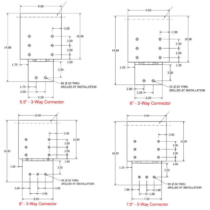
3-Way Connector Capacities
The beam and post parts of the connection are called out separately as there can be different combinations of sizes. Choose the lowest post/beam values for the connection conditions to apply to the connection as a whole.
The beam capacities are assumed per beam with two coming together over the post. If it is a continuous beam with 6 pins running over top, the capacities can be doubled; however, local timber failures need to be checked.
Swipe horizontally to view full engineering table →
| Post Size | # of Pins Each Beam |
# of Pins Column |
Timber Species | Load Duration, Cd3 |
T1a Reinforced |
T1 - 10”b Reduced for simulated notch |
T1 - 12”b Reduced for simulated notch |
T2 | V1 |
Dc Downward, bearing on cap plate |
|---|---|---|---|---|---|---|---|---|---|---|
| 5-1/2” Column 3-Way (12” Max Beam Depth) |
3 Each beam |
— | EWP (G=0.36) | 1 | 1,436 | 573 | 398 | 3,258 | — | 4,955 |
| DF (G=0.5) | 1 | 2,017 | 779 | 541 | 3,767 | — | 8,848 | |||
| R. Oak (G=0.67) | 1 | 2,806 | 710 | 493 | 3,767 | — | 11,326 | |||
| — | 2 Column |
EWP (G=0.36) | 1 | 3,041 | — | — | — | 1,346 | 8,848 | |
| DF (G=0.5) | 1 | 3,516 | — | — | — | 1,891 | 14,157 | |||
| R. Oak (G=0.67) | 1 | 3,516 | — | — | — | 2,630 | 10,972 | |||
| 6” Column 3-Way (12” Max Beam Depth) |
3 Each beam |
— | EWP (G=0.36) | 1 | 1,436 | 625 | 434 | 3,258 | — | 5,897 |
| DF (G=0.5) | 1 | 2,017 | 850 | 590 | 3,767 | — | 10,530 | |||
| R. Oak (G=0.67) | 1 | 2,806 | 775 | 538 | 3,767 | — | 13,478 | |||
| — | 2 Column |
EWP (G=0.36) | 1 | 3,041 | — | — | — | 1,346 | 10,530 | |
| DF (G=0.5) | 1 | 3,516 | — | — | — | 1,891 | 16,848 | |||
| R. Oak (G=0.67) | 1 | 3,516 | — | — | — | 2,630 | 13,057 | |||
| 7-1/2” Column 3-Way (12” Max Beam Depth) |
3 Each beam |
— | EWP (G=0.36) | 1 | 1,708 | 781 | 543 | 4,148 | — | 9,214 |
| DF (G=0.5) | 1 | 2,301 | 1,063 | 738 | 4,520 | — | 16,453 | |||
| R. Oak (G=0.67) | 1 | 2,806 | 969 | 673 | 4,520 | — | 21,060 | |||
| — | 3 Column |
EWP (G=0.36) | 1 | 4,840 | — | — | — | 2,511 | 16,453 | |
| DF (G=0.5) | 1 | 5,273 | — | — | — | 3,382 | 26,325 | |||
| R. Oak (G=0.67) | 1 | 5,273 | — | — | — | 4,124 | 20,402 | |||
| 8” Column 3-Way (12” Max Beam Depth) |
3 Each beam |
— | EWP (G=0.36) | 1 | 1,708 | 833 | 579 | 4,148 | — | 10,483 |
| DF (G=0.5) | 1 | 2,301 | 1,133 | 787 | 4,520 | — | 18,720 | |||
| R. Oak (G=0.67) | 1 | 2,806 | 1,033 | 718 | 4,520 | — | 23,962 | |||
| — | 3 Column |
EWP (G=0.36) | 1 | 4,840 | — | — | — | 2,562 | 18,720 | |
| DF (G=0.5) | 1 | 5,273 | — | — | — | 3,451 | 29,952 | |||
| R. Oak (G=0.67) | 1 | 5,273 | — | — | — | 4,209 | 23,213 | |||
| 10” Column 3-Way (12” Max Beam Depth) |
3 Each beam |
— | EWP (G=0.36) | 1 | 1,832 | 1,042 | 723 | 4,148 | — | 16,380 |
| DF (G=0.5) | 1 | 2,301 | 1,313 | 984 | 4,520 | — | 29,250 | |||
| R. Oak (G=0.67) | 1 | 2,806 | 1,197 | 897 | 4,520 | — | 37,440 | |||
| — | 3 Column |
EWP (G=0.36) | 1 | 4,840 | — | — | — | 2,748 | 29,250 | |
| DF (G=0.5) | 1 | 5,273 | — | — | — | 3,451 | 46,800 | |||
| R. Oak (G=0.67) | 1 | 5,273 | — | — | — | 4,209 | 36,270 |
Table 7 - 3-Way Connection Capacity1, Units: lb.
1 Capacities for species not shown may be linearly interpolated based on specific gravity.
2 Pins are ½” diameter and assumed to be 5” minimum length for 6x connectors and 7” minimum for 8x connectors.
3 Capacities can be adjusted for Load Duration Factors other than 1.0.
4 Assumes the beam and post are the same species.
5 Timbers that are full sawn or planed to ½” under have the same listed capacities assuming the same pin size.
6 Connectors and pins are 6061 aluminum.
7 EWP = Eastern White Pine, DF = Douglas-Fir-Larch, R. Oak = Red Oak.
8 Downward load of the connection is limited by the wood side grain crushing of the beams or the parallel-to-grain crushing of the post. Those values are specific to wood species, are not directly related to density, and are to be evaluated by the project engineer.
HDPE Risers
HDPE risers further provide a protective space between the post end and the concrete. The concrete lateral capacities of the connectors with these risers need to be determined with site specific information. The capacities of the timber component are the same as listed in Table 3. The compressive capacity of the riser matches or exceeds the available compressive capacity of the timber species listed. Please see HDPE Specs for risers by clicking here.